Factory Selling Armored Type Movable AC Metal-Enclosed Switchgear Supplier


Overview
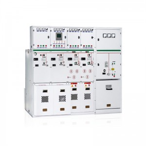
HXGN17-12 box-type fixed metal switchgear(referred to as switchgear for short)is used for receiving and distributing electric energy in3.6,7.2and 12KV three-phase AC 50Hz systemsespeciallysuitable for frequentoperation occasions.Its bus system is single bus (and can be derived from singlebus with bypass and doublebus structure).
This switch cabinet meets the requirements of national standard GB 3906″3-35 kV AC Metal Closed Switchgear”and international standard IEC298,and achieves the locking function of”Five Preventions”.
The main switch of this switch cabinet adopts ZN28A-12 or ZN22-12 series vacuum circuit breaker with CD17A electromagnetic operating mechanism and CT19B spring operating mechanism,and the isolating switch adopts GN30-12 rotary isolating switch and GN22-10 high current isolating switch series products.
Use environmental conditions
Ambient temperature:-25℃~+40℃;
Altitude≤1000M;
Relative environment humidity:The daily relative humidity average≤95%;The monthly relative humidity average≤90%;
The earthquake sintensity≤8 degree;
Without fire,the danger of explosion,chemical corrosion and fierce vibration place and the pollution grade not beyond 3 level.
Model and meaning

The main technical parameters
| Item | Unit | VS1 |
| Rated voltage | kV | 3.6、7.2、12 |
| Rated current | A | 630,1250,1600,2000,3150 |
| Rated short circuit breaking current | kA | 16,20,31.5,40 |
| Rated short circuit making current(peak value) | kA | 40,50,80,100 |
| Rated short circuit stable moving current(peak value) | kA | 40,50,80,100 |
| Rated heat stable heating current | kA | 16,20,31.5,40 |
| Rated heat stable heating time | s | 4 |
| Protection level | IP2X | |
| Structure type | Single bus bar disjunction and single bus bar with branches | |
| Operation mode | eletromagnetic,spring and energy storage type | |
| dimension width×deep×is high | mm | 1100×1200×2600(common type) |
| Weigh | kg | 1000 |
Structural features
HXGN17.12 switch cabinet is themetal-enclosed box structureits cabinet frame is welded together bv the anale ron.the cabinet inside is divided into breaker roombus bar room cable roomrelays room and so onRooms are separated by armor plate.
1.The circuit breaker room is located below in front of the cabinet bodyIt isconnected bythe tenion bar and the drive mechanism. Line terminal above the breaker connects with isolated switch.Line terminal blow the breaker connects with the current mutual inuctance which connects isolated switch line terminal.The circuit breaker room also isequipped with the pressure release chanel,ifintenal electric arc itoccurs,the gas passable exhaust channe released the pressure through exhaust channel.
2.Bus bar room is behind,upside cabinet body.In order to reduce the cabinet boy alitudebus bar room shows itself like the word”品”supported by the 7350N anticurved intensity prcelain insulator.Bus bar connects with upside insulated switch’s line terminal. Bus bar room in neighboring two cabinets can beisolable.
3.The cable room is behind and below the cabinet body.The supporting insulatr inside the cable room may be eauipped with the voltage monitor device.Te electric cable fixes on the support.When the main line is used to connect,this room is connecting cable room. The relay room is upside and in front ofhe cabinet bodyThe installig panel inside the cable room can install each kind of the relay.There are terminal supporters inside.The door ofthe cable room can be installed indication instrument,the signal part and other twice parts. The top can be installed twice small busbar.
4.Circuit breakers drive mechanism is installed face and left side of the breaker.Above it is isolated switchs operation and the interlockng mechanism. The switch cabinet is the two-sided maintenance.The front is twice component checking and repairing relay room and breaker, maintaining the drive mechanism,interlocking mechanism and transmission parts; the back is repairing the main bus bar and cable terminal.There is head lamp inside the breaker.The downside of front doorsequipped with bus bar connected by copper paralleling with cabinet.The section is 4x40mm.
5.Mechanical interlocking: In order to prevent the load from turning on and off the isolated switch and the circut breaker by mistake. prevent from isolating with charge and earthed switch with charge and turning on the knife switch.The switch cabinet uses the corresponding mechanical interlocking.The mechanical interlocking movement principle as follows:
(1)power-cut operation(operation-examination)
The switch cabinet is in the working position,namely the upside and downside isolated swiththe circuit breaker are at turn-on condition,the front and back door has been locked and atelectriferous condition,at this time,the small handle was in the working position.
First,turn the breaker off,insert the small landle into downside isolated operation holethen pull to the isolated turn-of position from down to up.Then take the handle downinsert the handle into upside isolated operation holepull to the solated turn-off position from up to down. Then take the handle down and insert it into switch hole,push from down to up to make the switch turn off.
At this time,pull the small handle to the”examination and repair condition.Then open the front doorfirst,then open the back door, the power cut operation finish,the examiner maintain and repair the breaker and the cable room
(2) Power transmission operation(examination repair-movement)
If examination repair operation has finishedthe power transmission isneededits operation procedure as follows:
Close the back door,after the key is taken outclose the front door,pull the small hande from”the examination repair” position to disjunction and closedown”position,at this time the front door is locked,the circuit breaker can not be turned on. Insert the operation handle to the earted switch operational hole.push theupside isolator to the turn on position from down to uptake the operation handle out and insert into the downside isolating operational hole,pull the downside isolator to the tum-on operation from down to up and take the operational handle out,pull the small handle to the operation position,at this time, turn the breaker on.
6.Products external dimensions and the structure chart(see chart1,chart2,chart 3)
Diagram 1 Dimension and structure of HXGN17-12 type

1.Main bodystructure
2.doorsearthed line
3.Secondearyelectriccableinstallment
4.Back door interconnection assembly
5.Head lamp
6.Support insulator
7. Overhead outgoing
8.Bus bar room assembly
9.Relay room assembly
10.Front doors component assembly
11.The isolated switch drive assembly with earth knife
12.Operation interlocking mechanism
13.Current transformer Downside isolated switch drive assembly
14.Assembly of current transformer
15.The vacuum circuit-breaker drive assembly
16.Earthed bus bar assembly
Diagram 2 ouline structure of HXGN17-12 heavy current cabinet(equipped with ZN28A series vacuum circuit breaker)

Diagram 3 outline structure of HXGN17-12 bypass cable outgoing cabinet 
Diagram 4 Mounting size of HXGN17-12 type

Diagram 5 Mounting size of HXGN17-12 type